STM32F407 QUADCOPTER

Flight Controller Development Log

I'm documenting the process of building a quadcopter flight controller from the peripheral level upward: drivers, sensors, estimation, control and eventually flight.

DEVELOPMENT LOG 003

When SPI Disappears: Debugging Communication Between an STM32 and Arduino

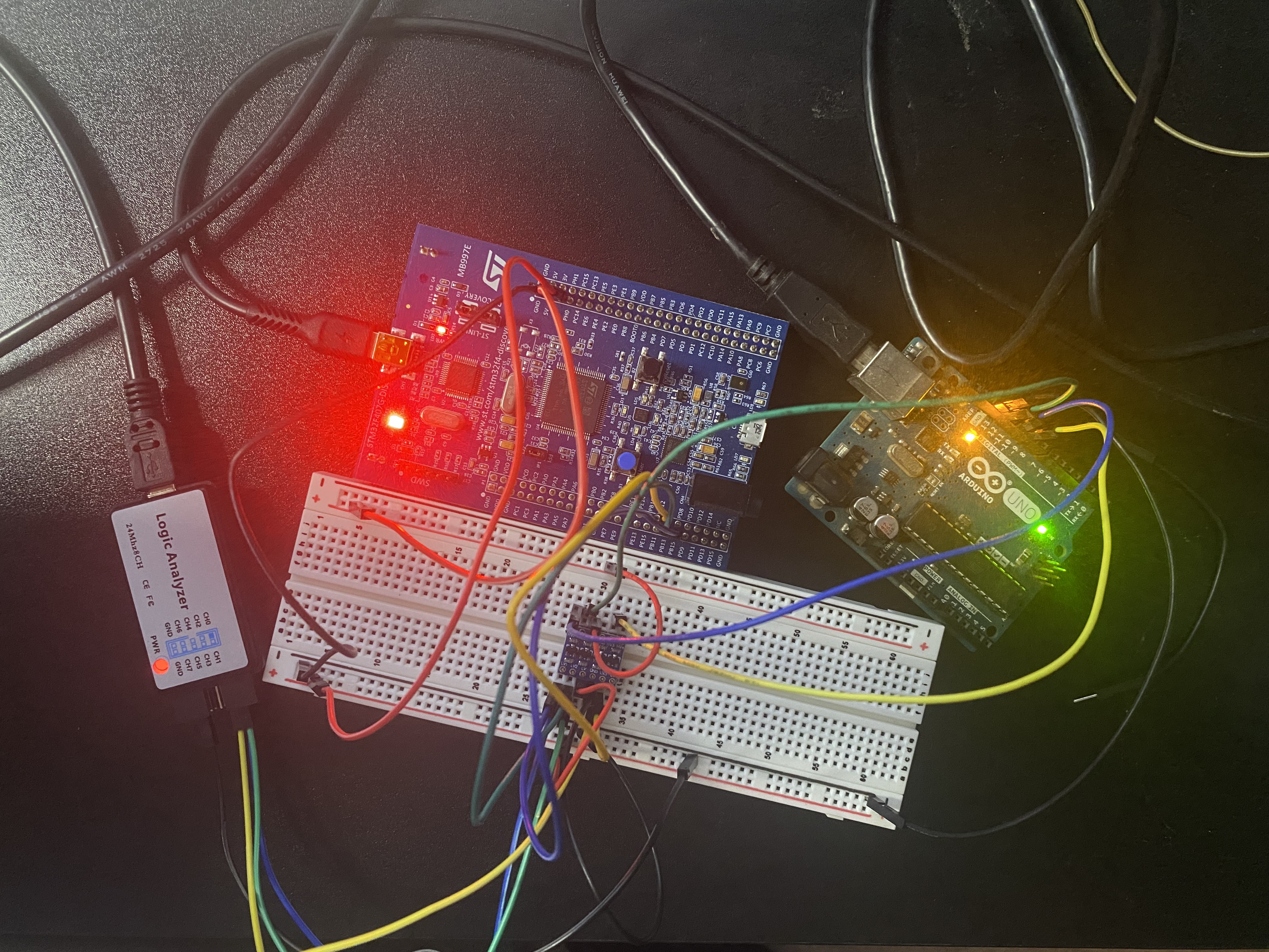
STM32F407 and Arduino connected through a breadboard for SPI testing
The STM32F407 and Arduino test setup during SPI communication debugging.

After validating my STM32F407 SPI driver with a logic analyzer, the next step was connecting the STM32 to another device. I chose an Arduino as the SPI slave. What looked like a straightforward integration quickly became a hardware debugging exercise when signals that were clearly leaving the STM32 were no longer reaching the Arduino.

Eventually I want to add a camera to my quadcopter and I will likely need another microcontroller to process the video. So I need to figure out master and slave communication.

This ended up being one of the more useful tests in the project so far. The problem was not simply solved by changing code. I had to follow the signals physically through the circuit and determine exactly where they disappeared.

The Goal

My previous SPI test transmitted "Hello World" from SPI2 on the STM32F407 and verified the output with a logic analyzer.

That proved that the STM32 could generate the expected SPI clock and data. Now I wanted to move from observing the bus to communicating with an actual slave device.

1 STM32F407
→
2 SPI
→
3 Arduino

The STM32 would operate as the SPI master and the Arduino as the slave.

Connecting the Two Boards

SPI requires several signals to be shared between the master and slave. For this test I needed the clock, master output, slave output and slave select signals along with a common ground reference.

SPI Connections

STM32 SCLK → Arduino SCK
STM32 MOSI → Arduino MOSI
STM32 MISO ← Arduino MISO
STM32 NSS → Arduino SS
STM32 GND ↔ Arduino GND

I initially routed the signals through the breadboard and the interface hardware between the two boards. With everything connected, I programmed both devices and started checking the bus with the logic analyzer.

First Question: Is the STM32 Actually Transmitting?

When communication between two devices fails, there are immediately several possible causes. The master may not be transmitting. The slave may be configured incorrectly. The SPI modes may not match. Slave select may not be asserted correctly. There may also simply be a wiring problem.

Instead of changing several things at once, I started with the side of the system I had already tested: the STM32.
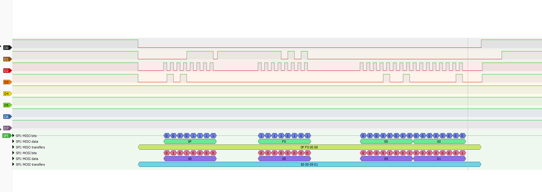
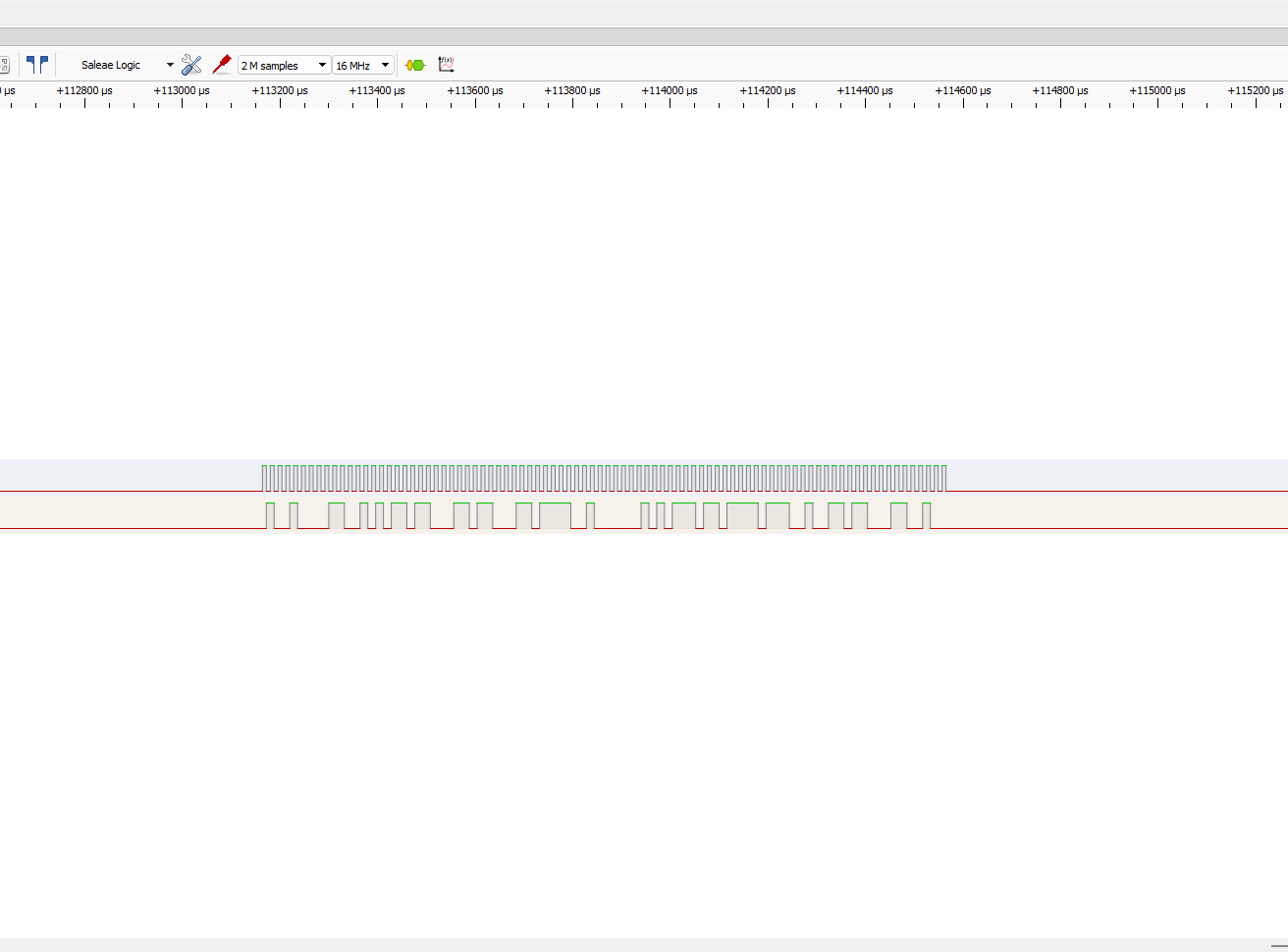
Logic analyzer trace showing SPI signals and decoded data from the STM32F407
Probing the STM32 side showed the expected SPI activity. The clock and transmitted data were present and the analyzer could decode the traffic.

This was an important result because it reduced the search space. I already knew from the previous "Hello World" test that my SPI driver could generate valid signals. Seeing those signals again told me that the STM32 peripheral was still operating.

Debugging Principle

Verify what is known to work before changing it. If the expected signal exists at the source, start following that signal toward the destination.

Following the Signal

This is where the logic analyzer became particularly useful.

Instead of only connecting the analyzer at one location, I moved the probes along the physical signal path. Close to the STM32, I could measure the expected SPI activity. I then moved the probes to the other side of the circuit closer to the wires leading to the Arduino.

The result changed.
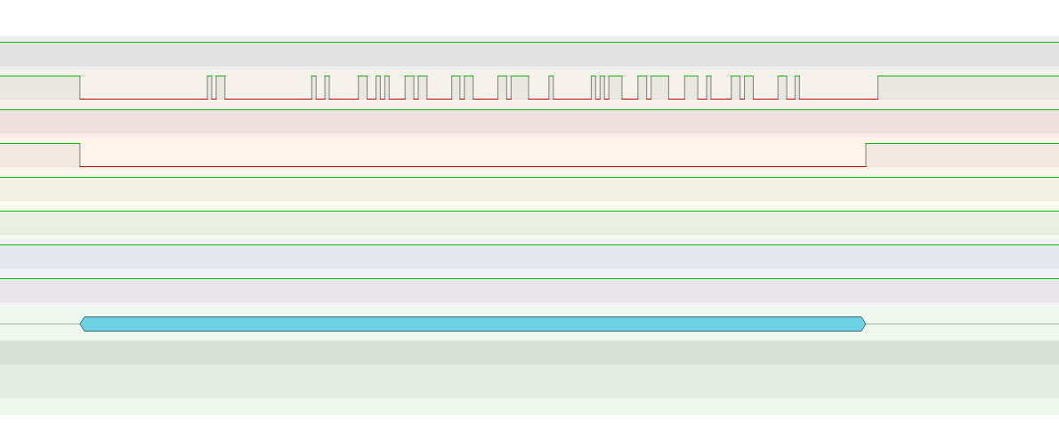
Logic analyzer capture showing one SPI signal while other expected signals are missing
After moving the analyzer probes to the Arduino side of the signal path, only one of the expected signals remained visible while the others disappeared.

This was the critical observation.

The firmware had not changed. The SPI configuration had not changed. The STM32 was still generating the signals. The only thing that changed was where I measured them.

That meant I was no longer primarily debugging the SPI peripheral. I was debugging the physical path between the two boards.

The Signal Exists Here, But Not There

At this point the circuit effectively gave me two observations:

✓ STM32 Side
→
? Interface
→
✕ Arduino Side

The same signal that was measurable before passing through the interface was missing afterward.

The breadboard connections, jumper wires and level shifting interface therefore became much more interesting than the SPI code.

Isolating the Interface

The two boards operate with different logic voltage conventions, so I had originally included level shifting hardware between them. That also introduced another component into every signal path.

At this point I needed to determine whether that interface was actually helping the communication or preventing it.

Since the analyzer showed valid signals before the interface and missing signals after it, I tested the connection without that part of the signal path.

Simplifying the Circuit
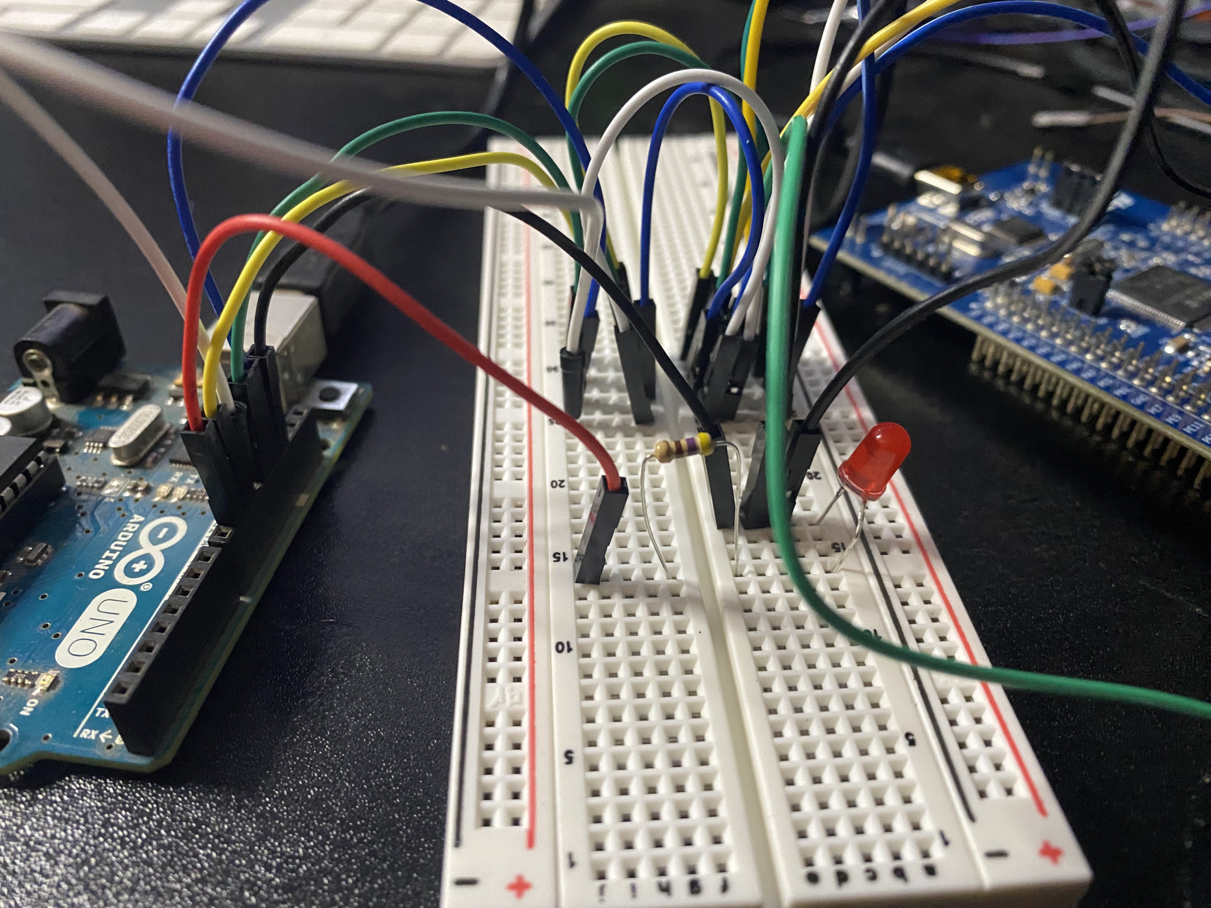
STM32F407 connected directly to an Arduino for SPI communication
The simplified final test setup with the STM32F407 and Arduino connected directly for SPI communication.

Bypassing the problematic portion of the interface restored communication.

That result confirmed what the earlier measurements had suggested: the SPI peripheral itself was not the source of the failure. The problem was in the physical signal path between the STM32 and Arduino.

What Actually Solved the Problem

The useful part of this test was not any single code change. It was the process of progressively reducing the number of possible causes.

1 Observe Failure
→
2 Verify Source
→
3 Move Probe
→
4 Locate Failure
→
5 Isolate

First, I verified that the STM32 was still producing the expected SPI signals. Then I measured the same signals at another point in the circuit. When the behavior changed depending on the measurement location I could stop treating the firmware as the most likely problem.

From there, simplifying the physical connection allowed me to isolate the component that was interfering with the signal path.

The Bigger Lesson

Embedded debugging crosses the boundary between software and hardware.

When the Arduino was not receiving the expected SPI communication it would have been easy to keep changing register settings or rewriting the transmit code. But software changes would not fix a signal that was being lost after it left the microcontroller.

Being able to probe the bus at multiple physical points turned an ambiguous communication failure into a much more specific question:

Where does the signal stop looking correct?

Once I could answer that question the problem became considerably easier to isolate.

That is a debugging technique I expect to use repeatedly as the quadcopter becomes more complex. Verify each layer independently and follow failures across the boundary between software and hardware rather than assuming which side is responsible.

Building Toward the Flight Controller

The Arduino is serving as a useful development target while I build and test the STM32 communication stack. The larger objective is still the quadcopter flight controller.

Developing a repeatable debugging process now is just as important as developing the drivers themselves.

At this stage, another piece of the system has moved from "the code should work" to something much more useful: behavior I have actually observed and validated on the hardware.
PROJECT SOURCE STM32F407 Quadcopter
View on GitHub →

DEVELOPMENT LOG 002

"Hello World" Over SPI: STM32F407 Driver With a Logic Analyzer

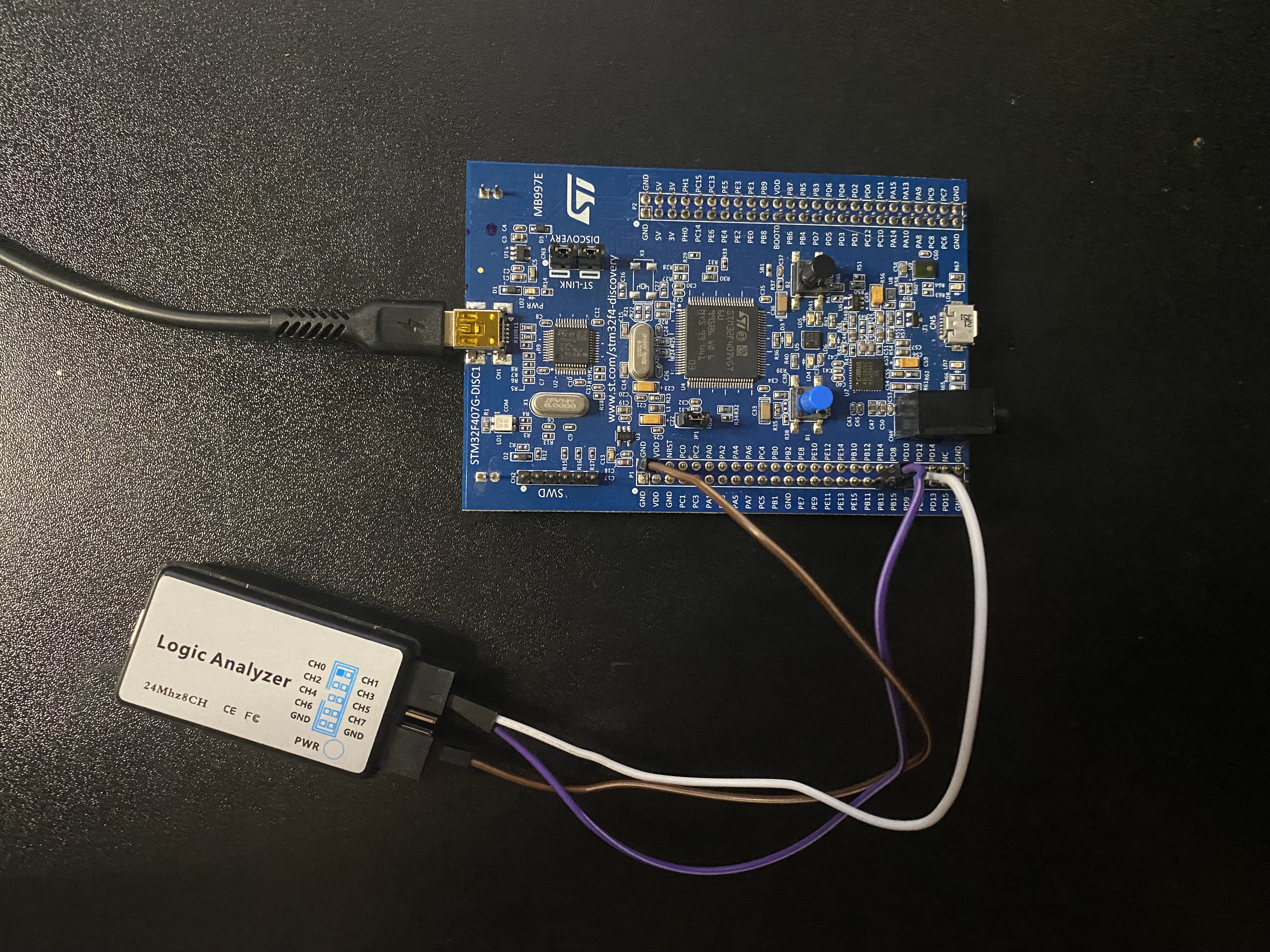
STM32F407 development board connected to a logic analyzer for SPI testing
STM32F407 connected to a logic analyzer while testing my SPI2 driver.

After getting GPIO and external interrupts working on the STM32F407 I moved on to serial communication. For this test I configured the STM32's SPI2 peripheral and transmitted "Hello World" using my own SPI driver. I then connected a logic analyzer to verify what was actually happening on the physical pins.

"Hello World" is obviously not the final purpose of the SPI driver but gives me something much more useful at this stage of the project: a known sequence of bytes that I can transmit and compare against a physical measurement.

Rather than connecting another SPI device immediately I wanted to validate the STM32 side first. That means checking the GPIO configuration and then the SPI peripheral configuration. Next clock generation and transmitted data, before adding another piece of hardware to the system.

Moving From GPIO to Serial Communication

My previous test focused on GPIO and interrupts. A button changed the electrical state of an input pin, the STM32 detected the event through the EXTI peripheral and an interrupt service routine toggled an LED.

SPI introduces another level of complexity; instead of interpreting a single HIGH or LOW state the microcontroller uses coordinated clock and data signals to transfer a sequence of bits between devices.

1 C String
→
2 SPI Driver
→
3 SPI2
→
4 Physical Pins
→
5 Logic Analyzer

The Hardware Test Setup

I connected the logic analyzer directly to the STM32F407 so I could observe the signals produced by SPI2.

Physical STM32F407 and logic analyzer setup used to test SPI communication
The physical test setup: The logic analyzer is connected to the STM32F407.

For this transmit only test the two important signals are SCLK and MOSI. The STM32 is acting as the SPI master so it generates the clock and places outgoing data onto MOSI.

SPI2 Test Connections

PB13 → SPI2 SCLK
PB15 → SPI2 MOSI
Logic Analyzer GND → STM32 GND

MISO is not needed for this particular test because nothing is being transmitted back to the STM32. The purpose here is specifically to validate the transmit path.

Giving SPI2 Control of the GPIO Pins

Before SPI2 can generate a clock or transmit data the appropriate GPIO pins need to be connected internally to the SPI peripheral.

On the STM32F407G this is done by configuring the pins for alternate function mode and selecting the appropriate alternate function.

void SPI2_GPIOInits(void)
{
    GPIO_Handle_t SPIPins;

    SPIPins.pGPIOx = GPIOB;

    SPIPins.GPIO_PinConfig.GPIO_PinMode =
        GPIO_MODE_ALTFN;

    SPIPins.GPIO_PinConfig.GPIO_PinAltFunMode =
        5;

    SPIPins.GPIO_PinConfig.GPIO_PinOPType =
        GPIO_OP_TYPE_PP;

    SPIPins.GPIO_PinConfig.GPIO_PinPuPdControl =
        GPIO_NO_PUPD;

    SPIPins.GPIO_PinConfig.GPIO_PinSpeed =
        GPIO_SPEED_FAST;

    // SPI2 SCLK
    SPIPins.GPIO_PinConfig.GPIO_PinNumber =
        GPIO_PIN_NO_13;

    GPIO_Init(&SPIPins);

    // SPI2 MOSI
    SPIPins.GPIO_PinConfig.GPIO_PinNumber =
        GPIO_PIN_NO_15;

    GPIO_Init(&SPIPins);
}

PB13 provides the SPI2 clock and PB15 provides MOSI. Both are configured for Alternate Function 5 which connects those physical pins to the SPI2 peripheral.

Configuring SPI2

Once the pins are configured I initialize SPI2 using the SPI driver I wrote for the project.

void SPI2_Inits(void)
{
    SPI_Handle_t SPI2handle;

    SPI2handle.pSPIx = SPI2;

    SPI2handle.SPIConfig.SPI_BusConfig =
        SPI_BUS_CONFIG_FD;

    SPI2handle.SPIConfig.SPI_DeviceMode =
        SPI_DEVICE_MODE_MASTER;

    SPI2handle.SPIConfig.SPI_SclkSpeed =
        SPI_SCLK_SPEED_DIV256;

    SPI2handle.SPIConfig.SPI_DFF =
        SPI_DFF_8BITS;

    SPI2handle.SPIConfig.SPI_CPOL =
        SPI_CPOL_LOW;

    SPI2handle.SPIConfig.SPI_CPHA =
        SPI_CPHA_LOW;

    SPI2handle.SPIConfig.SPI_SSM =
        SPI_SSM_EN;

    SPI_Init(&SPI2handle);
}
SPI2 Configuration

Device → Master
Bus → Full Duplex
Frame Size → 8 bits
Clock Speed → Peripheral Clock / 256
CPOL → Low
CPHA → Low
Software Slave Management → Enabled

I am using 8 bit frames because each character in the test message can be transmitted as a byte. The STM32 is configured as the master; meaning it is responsible for generating SCLK.

Sending "Hello World"

Once the GPIO and SPI configuration is complete I can enable the peripheral and pass the message to my SPI transmit function.

int main(void)
{
    char user_data[] = "Hello World";

    SPI2_GPIOInits();

    SPI2_Inits();

    SPI_SSIConfig(SPI2, ENABLE);

    SPI_PeripheralControl(
        SPI2,
        ENABLE
    );

    SPI_SendData(
        SPI2,
        (uint8_t *)user_data,
        strlen(user_data)
    );

    SPI_PeripheralControl(
        SPI2,
        DISABLE
    );

    while (1);
}

At the software level I am passing a pointer to the message along with its length. Inside the driver those bytes are written to the SPI data register and the peripheral handles shifting them onto MOSI.

"Hello World" Is Really Just Bytes

The SPI peripheral has no concept of words or text. "Hello World" is useful to me as a human but SPI only sees the underlying binary values.

H       0x48
e       0x65
l       0x6C
l       0x6C
o       0x6F
space   0x20
W       0x57
o       0x6F
r       0x72
l       0x6C
d       0x64

These are the values I expect the logic analyzer to reconstruct from the electrical signal generated on MOSI.

Capturing the Transmission

After programming the STM32 I captured SCLK and MOSI with the logic analyzer and configured the software to decode the signals as SPI.

Logic analyzer SPI trace showing Hello World transmitted from an STM32F407
The complete SPI capture.

This is the point where the test becomes much more meaningful than simply seeing the firmware execute. The analyzer is observing the actual voltage transitions produced by the microcontroller and reconstructing the bytes from them.

The original message has now traveled through several layers:

1 Memory
→
2 My Driver
→
3 SPI2
→
4 MOSI
→
5 Decoder

Seeing "Hello World" reconstructed at the other end gives me confidence that those layers are working together correctly.

Looking at the Individual Clock Edges

The decoded message verifies the complete transmission but I also wanted to look at the raw waveform more closely.

Zoomed SPI logic analyzer waveform showing the relationship between the clock edge and MOSI data
A closer look at the SPI waveform showing the clock edge and the corresponding state of the MOSI signal.

This matters because SPI communication depends on the relationship between the clock and the data signal. Two configuration values, "CPOL and CPHA", define that relationship.

SPI2handle.SPIConfig.SPI_CPOL =
    SPI_CPOL_LOW;

SPI2handle.SPIConfig.SPI_CPHA =
    SPI_CPHA_LOW;

CPOL controls the idle state of the clock. With CPOL low SCLK rests at logic LOW when the bus is inactive.

CPHA determines which clock transition is used when sampling data. With CPHA low data is sampled on the first clock edge and changes on the following edge. Because CPOL is also low in this configuration the first edge is the rising edge and the following edge is the falling edge.

Looking at the falling edge in the capture therefore gives me a way to inspect the timing relationship between SCLK and MOSI instead of relying entirely on the protocol decoder.

SPI Mode Used in This Test

CPOL = 0 → Clock idles LOW
CPHA = 0 → Sample on the first edge
First edge → Rising
Following edge → Falling

Why Use a Logic Analyzer?

One of the biggest differences I have found between ordinary software development and embedded development is that correct looking source code does not necessarily mean correct hardware behavior.

I could make a mistake selecting an alternate function, configuring the SPI clock, setting CPOL or CPHA or manipulating a peripheral register and still have code that compiles without an error.

The logic analyzer gives me an independent way to verify what the microcontroller is actually doing.

1 Configure
→
2 Transmit
→
3 Measure
→
4 Decode
→
5 Validate

In this case I can verify both the high level result "Hello World" and the low level clock and data relationship that produced it.

Why This Matters for the Quadcopter

The goal of this project is not to make an STM32 print "Hello World." The goal is to build a flight controller whose software I understand from the peripheral level upward.

Eventually the STM32 will need to communicate reliably with sensors and other hardware while simultaneously processing measurements, estimating the orientation of the aircraft, running control algorithms and generating motor commands.

Debugging that complete system would be significantly harder if I did not already trust the communication drivers underneath it.

My approach is therefore to test each subsystem independently. I write the driver, create a simple test, measure the actual hardware behavior and verify that it matches what I expected before moving on.

GPIO and interrupts were the first step. Successfully transmitting and measuring SPI data gives the flight controller another working piece of its low level foundation.

SOURCE CODE 006spi_tx_tesing.c
View on GitHub →

DEVELOPMENT LOG 001

Redesigning the Quadcopter:
Bare Metal Programming

STM32F407 connected to a breadboard for GPIO interrupt testing
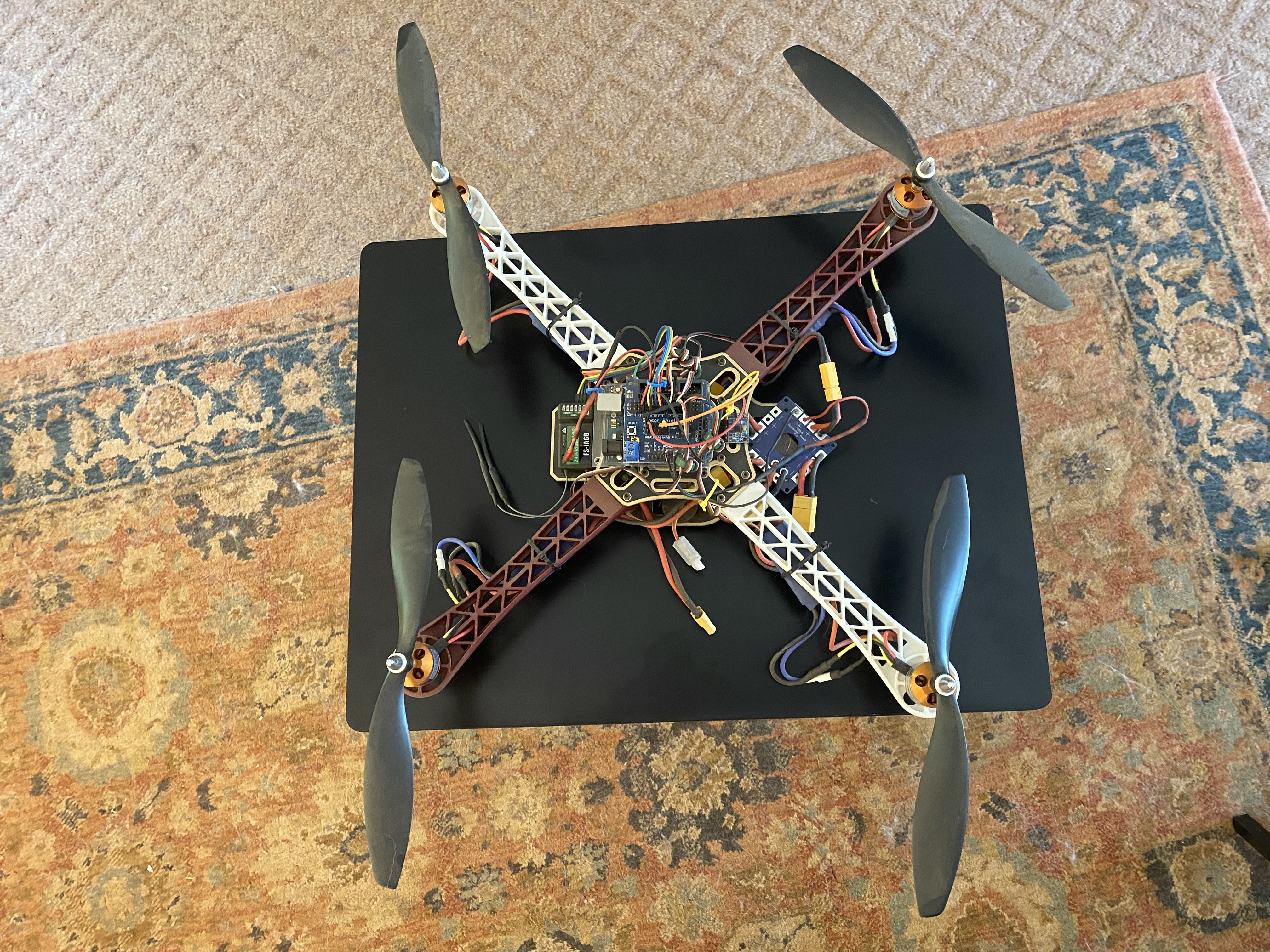
Original Quadcopter built with Arduino.

Original Design

A couple of years ago I built a self balancing quadcopter with arduino and it's built in libraries. While this was no small feat to buy the individual parts, learn about PID and program it, I want to redesign the entire system.

This time I want to program the system bare metal. This means writing all the drivers, libraries and the flight controller.

Before I can read sensors, control motors or implement a flight controller, the STM32 needs a reliable way to interact with the hardware around it.

One of the first pieces of the flight-controller stack I've implemented is a GPIO driver. GPIO, or General Purpose Input/Output, gives the microcontroller a basic interface to external hardware.

For this test I connected a button and LED to the STM32F407 and configured the input to generate an external interrupt. Instead of continuously checking whether the button is pressed, the processor can be interrupted when the event actually occurs.

Why Use an Interrupt?

The simplest way to detect a button would be polling. The processor could continuously read the GPIO pin:

while (1)
{
    if (GPIO_ReadFromInputPin(GPIOA, GPIO_PIN_NO_5))
    {
        GPIO_ToggleOutputPin(
            GPIOD,
            GPIO_PIN_NO_12
        );
    }
}

That approach works, but the processor has to repeatedly check the input whether anything is happening or not.

With an interrupt, hardware detects the configured event and notifies the processor. Execution temporarily jumps to an interrupt service routine, handles the event and then returns to whatever code was previously executing.

1 Button
→
2 GPIO
→
3 EXTI
→
4 NVIC
→
5 ISR

Configuring the GPIO

My GPIO driver uses a handle containing the GPIO peripheral and the configuration for the individual pin.

GPIO_Handle_t GPIOBtn;

GPIOBtn.pGPIOx = GPIOA;

GPIOBtn.GPIO_PinConfig.GPIO_PinNumber =
    GPIO_PIN_NO_5;

GPIOBtn.GPIO_PinConfig.GPIO_PinMode =
    GPIO_MODE_IT_FT;

GPIOBtn.GPIO_PinConfig.GPIO_PinSpeed =
    GPIO_SPEED_FAST;

GPIOBtn.GPIO_PinConfig.GPIO_PinPuPdControl =
    GPIO_PIN_PU;

GPIO_Init(&GPIOBtn);

In this case, the pin is configured as an interrupt input triggered by a falling edge.

Falling Edge

A falling-edge event occurs when the signal changes from a logic HIGH state to a logic LOW state.

Handling the Interrupt

Once the configured external interrupt fires, execution enters the appropriate interrupt handler:

void EXTI9_5_IRQHandler(void)
{
    GPIO_IRQHandling(GPIO_PIN_NO_5);

    GPIO_ToggleOutputPin(
        GPIOD,
        GPIO_PIN_NO_12
    );
}

The first operation clears the pending interrupt flag. The LED output is then toggled before returning from the handler.

Keeping an interrupt handler short is important. An ISR prevents normal execution from continuing while it runs, so lengthy processing inside the handler can interfere with other time-sensitive work.

Hardware Test

This is the actual GPIO interrupt running on the STM32F407 development board.

Why This Matters for the Quadcopter

Toggling an LED obviously isn't the final objective. This is a small hardware test for infrastructure that becomes much more important as the flight controller develops.

A flight controller needs to react to hardware events while simultaneously performing sensor acquisition, state estimation, control calculations and motor output.

Interrupts provide one of the mechanisms that allows the STM32 to respond to those events efficiently without continuously polling every peripheral.

SOURCE CODE 005button_interrupt.c
View on GitHub →